


Deve's Technical Network
1947-1955 1st Chevy Trucks
216/235/261 Engine Solutions & More
Following these procedures will guide you in correctly indexing the distributor assembly and initially setting the ignition timing advance.
1: The first step in this procedure is to insure that the #1 piston is brought to the top dead center (TDC) firing position. The firing position is TDC between the piston’s upward compression stroke and the subsequent downward power stroke. To achieve # 1 TDC firing position, perform either one of the following tasks.
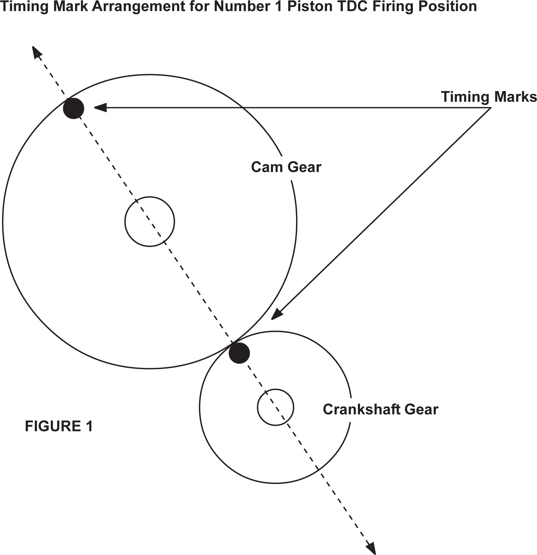
If the timing gears are exposed, rotate the crankshaft to bring the crank and cam gear timing marks as indicated in Figure 1. When viewing the gears from the front, the timing mark on each timing gear should be at approximately the 10 o’clock position. To precisely verify TDC, use any suitable straight edge through the center holes of the gears and the timing marks (see dotted line in Figure 1). This properly indexes the camshaft/crankshaft to #1 TDC firing position.
If the timing gears are not exposed, properly indexing the camshaft must be done by carefully viewing the lifters (preferred) and/or valve train. Start this procedure by rotating the crankshaft to bring the #1 piston to TDC (approximate). This can be achieved by viewing through the spark plug hole or by inserting a drinking straw or similar tool into the spark plug hole to help indicate TDC. The flywheel markings and bell-housing pointer can also be used for this purpose if those components have been installed on the engine. Notice that #1 and #6 pistons are at TDC together. One of these two cylinders will be TDC in between the compression and power stroke (firing position) and the other cylinder will be TDC in between the exhaust and intake stroke. To determine which cylinder is firing, rotate (rock) the crankshaft approximately 20 degrees CW and CCW to either side of TDC. Carefully watch the lifters (or valve train) of the #1 and #6 cylinders while rocking the crankshaft. You will notice that the intake and exhaust lifters of one of the cylinders will “alternate” up and down while neither lifter of the other cylinder will move up or down. The cylinder whose intake and exhaust lifters alternate up and down is the cylinder positioned in between the exhaust and intake strokes. The cylinder whose lifters do not move is the cylinder in the firing position. If necessary, rotate the crankshaft to bring the #1 cylinder into the TDC firing position. To finish this step, carefully bring the #1 piston as close as possible to exact (true) TDC. Using any suitable tool in the spark plug hole, you will notice that when the piston is at TDC there will be approximately 5 degrees of crankshaft movement possible (CW/CCW) to either side of true TDC that the piston has no discernible stroke movement. Find the “exact” middle of this movement and that will be true TDC.
2: The second step is to install the distributor assembly into the engine block. The end result will be threefold;
the distributor rotor tip will point to 6 o’clock (at 90 degrees to the crankshaft center line and away from the engine block);
the distributor cap spring clamps will be fore and aft (approximately parallel to the engine block);
the mounting plate adjustment slot will properly align with the mounting hole.
Prior to installing the distributor, three preparation steps are necessary;
if the oil pump has already been installed, locate the oil pump’s drive slot to the 1 and 7 o’clock position to aid in drive engagement;
loosen the vacuum advance mounting clamp that secures the mechanism to the distributor housing;
contact points must be installed and properly gapped at .016”.
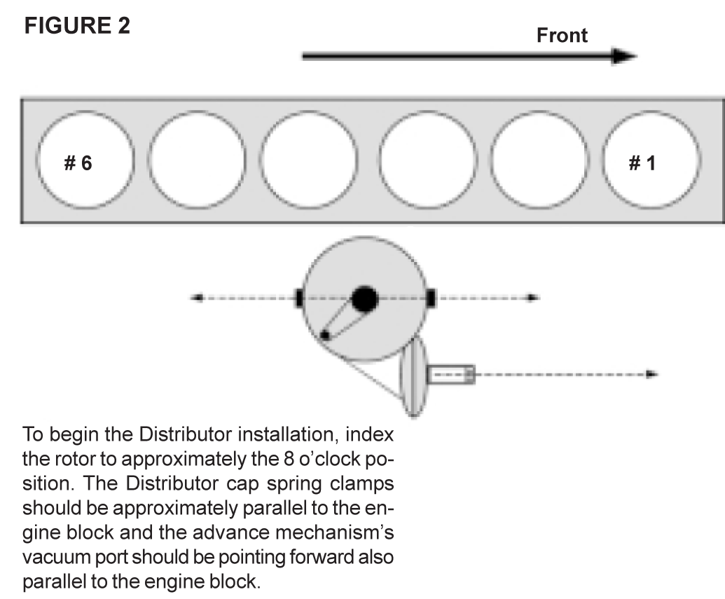
To install the distributor, proceed as follows. With a rotor installed on the distributor shaft for reference, index the rotor to approximately the 8 o’clock position. The distributor cap spring clamps should be approximately parallel to the engine block and the advance mechanism’s vacuum port should be pointing forward also parallel to the engine block (see Figure 2).
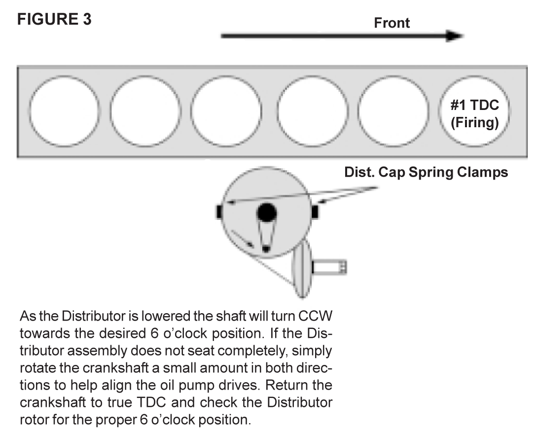
Insert the distributor into the engine block. Slight adjustments of the distributor shaft may be necessary to engage the cam gear. As the distributor is lowered and the shaft gear engages the cam gear, the distributor shaft will turn CCW towards the desired 6 o’clock position. If the distributor assembly does not seat completely, readjustment of the oil pump drive may be necessary or apply downward pressure to the distributor and simply rotate the crankshaft a small amount in both directions to help align the oil pump drives. Return the crankshaft to true TDC and check the distributor rotor for the proper 6 o’clock position (see Figure 3).
If the distributor seats completely but the rotor did not relocate into the 6 o’clock position, retry the installation after making the appropriate adjustments to the rotor’s starting position. When completed, verify that the crankshaft is at true TDC and that the distributor rotor is at the 6 o’clock position.
Center the mounting plate’s adjustment slot over the mounting hole and fasten with the bolt, or if this mounting plate is engraved with timing marks, align 0 degrees with the scribe mark (if visible), then fasten with bolt. The final task is to static time the ignition by properly indexing the contact points rubbing block with reference to the lobe on the distributor cam. The vacuum advance mounting clamp must be loosened and contact points must be installed and properly gapped at .016” to proceed.
With the distributor cap spring clamps approximately inline with the engine block (Figure 3) rotate the distributor housing clockwise until the rubbing block falls away from the lobe crown (points closed). Now, carefully rotate the distributor housing counter-clockwise until the points just open. Judging when the points just open can be done with some difficulty by eye but can be done very precisely with an ohmmeter across the point set.
When the correct distributor position has been determined, tighten the vacuum advance clamp. With some regard to how accurately these steps were performed, the ignition timing is now set to TDC or 0 degrees. To finish and bring the ignition timing to the recommended specification, loosen the previously mentioned fastening bolt at the adjustment slot and rotate the distributor and advance mechanism counter-clockwise 5 degrees (or your preference) as indicated by the engraved timing marks.
The distributor is now correctly indexed with the correct amount of ignition timing advance. The #1 cylinder spark plug wire is now located at 6 o’clock with the firing order (153624) proceeding clockwise around the cap. When possible, recheck the ignition timing (per manual) with a timing light.