


Deve's Technical Network
1947-1955 1st Chevy Trucks
216/235/261 Engine Solutions & More
The Advance Design Era was the last to have the tall radiator which presents a problem when going to the newer 1955-1962 235/261 engines. Because they changed the location of the waterpump for 1955-1962 to be 3" lower than the engines that came in an AD truck, our cooling fan is no longer in the center of the radiator. This reduces the cooling effect of the fan enough to be cause for concern. Look at the pictures and see the difference.
In addition to this problem, the newer engines were equipped with longer waterpump/shaft arrangements and presented a dilemna. Some people did the right thing and purchased a short shaft pump, or modified the original by pressing the hub further back and cutting off the excess shaft. Others did the WRONG thing and pulled the radiator and relocated it further forward requiring cutting into the front pan sheet metal. We see this a lot! This solution resolves both of these issues.
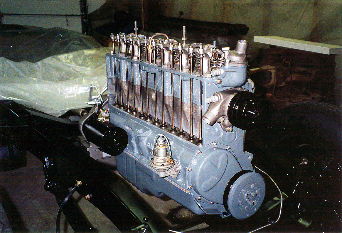
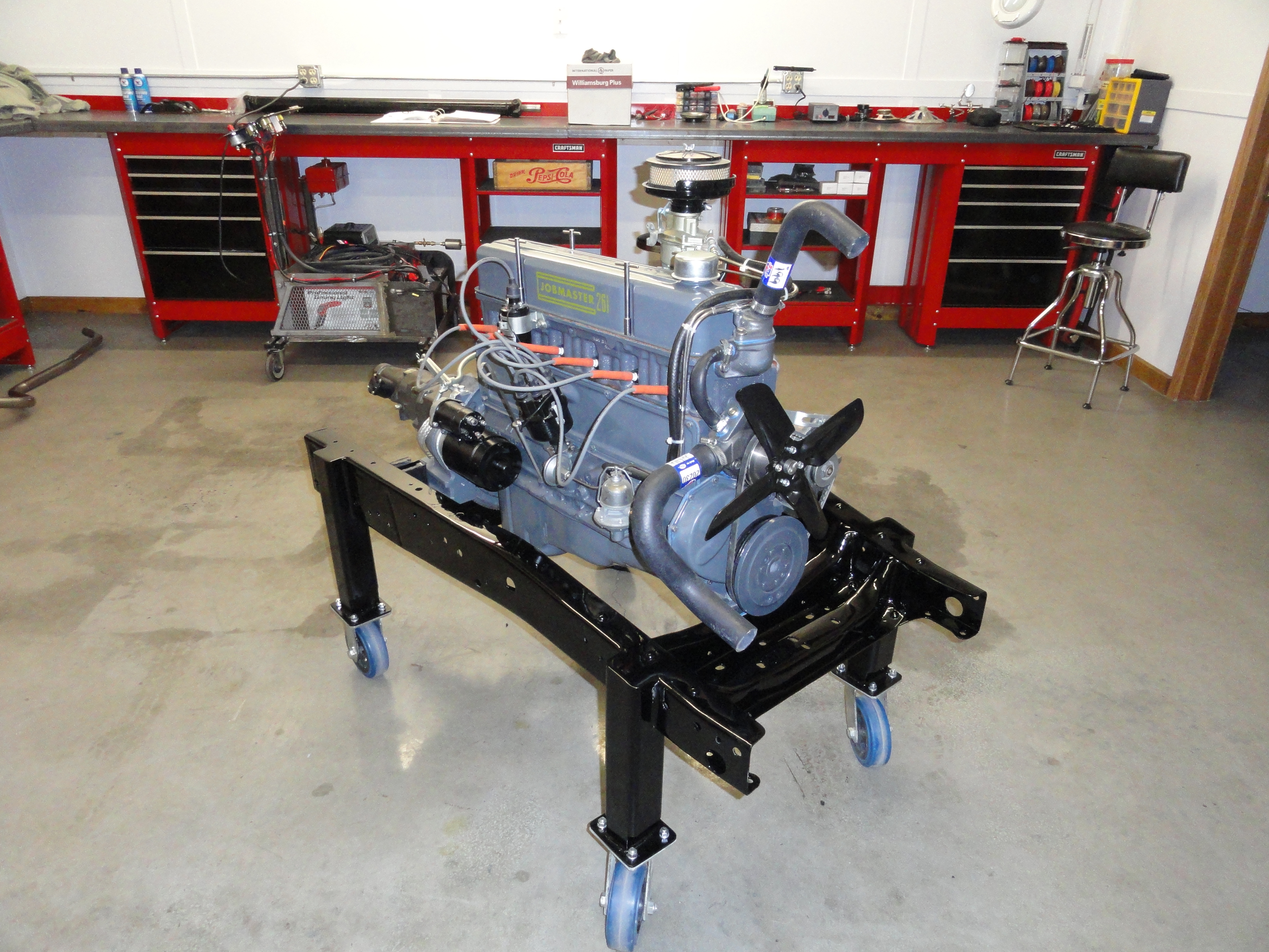
Shown left is a 1950 216 engine showing the waterpump is located high and on the right is an unmodified 261 from 1962 (same as a 1955-1962 235) with the waterpump location 3 inches lower from the factory. This lower waterpump was introduced in 1955 and is why we need Dave's adapter plate.
To fix this problem, Dave Folsom, a well known old Chevy Mechanic and Engineer came up with a Water Pump Adapter Plate that relocates the water pump on the 55-62 engines to accommodate the taller radiator. To install this adapter plate, two additional holes are drilled in the engine block and tapped for 3/8-16 bolts. With the waterpump in its original position for our trucks, we then install a 1953 216 waterpump and the original 216 fan. This keeps everything the 1/2" fan belt width and provides for the shorter shaft required for fitment without relocating the radiator further forward.
This is the best way to do this because the waterpumps are inexpensive and easily obtainable and with optimal cooling. To purchase the adapter plate, go to Ebay and type in the search box "1955-1962 Chevrolet 235 261 Water Pump Adapter". Dave charges about $40 for that. Then go to Rockauto.com and do a part number search for AW-108N (Airtex brand) and purchase the waterpump. The part number at oldchevytrucks.com (Jim Carter Truck Parts) for the 216 fan is MEE243. I get the fan belt from NAPA. It's the NAPA Premium 25-7440. The reason for using Rockauto is because they are about half the price of most of our vendors.
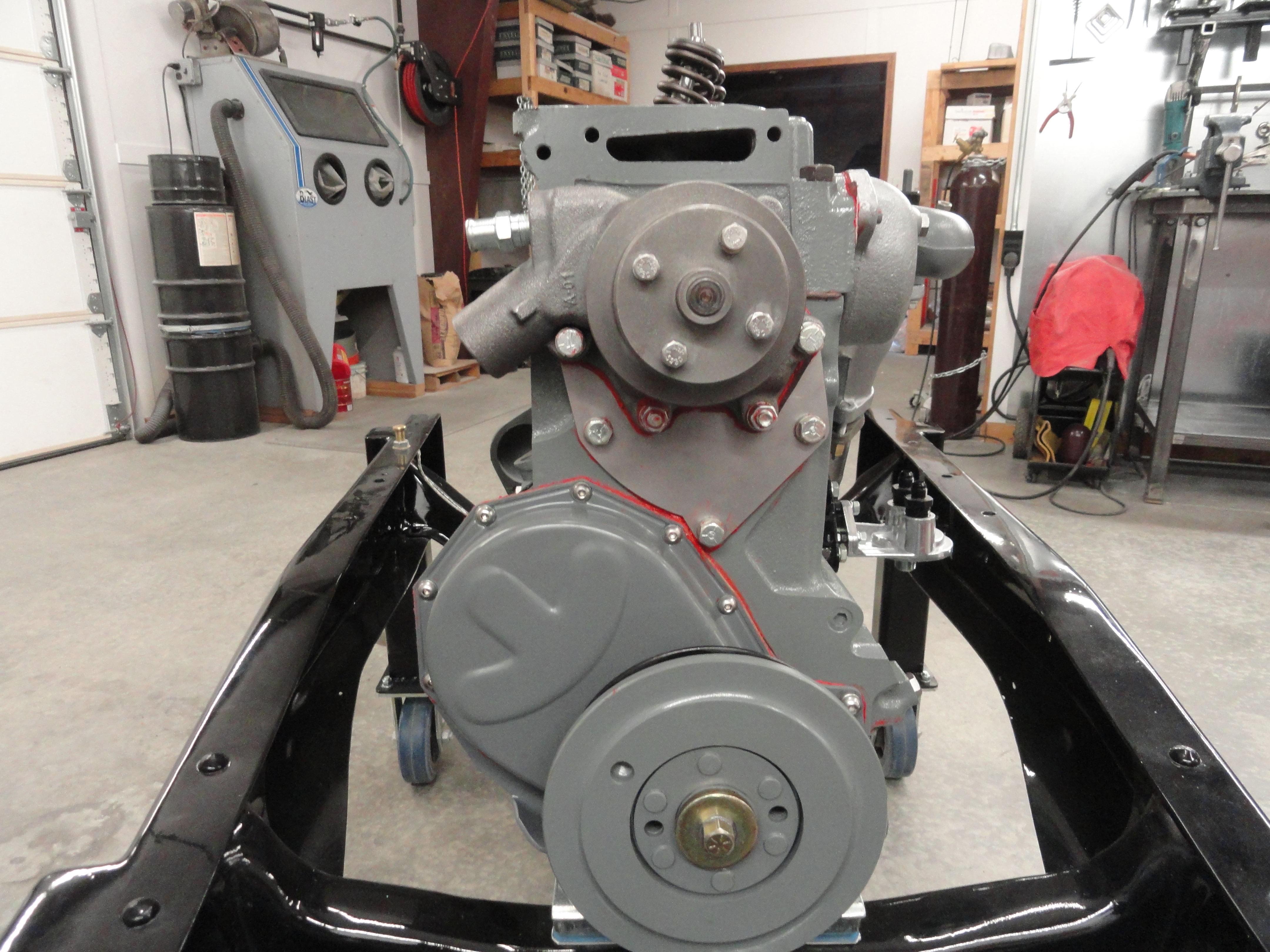
Shown left is the adapter plate installed. From the previous pictures, you can see why this is necessary. The other huge benefit is the shorter waterpump thus allowing us to install the engine with no problems in our Advance Design Chevy Trucks!
Overview: To install the adapter you will need a 5/16" drill bit with a piece of tape at 3/4" depth so you know where to stop, then a 3/8-16 tap. It is best to use a bottoming tap for this. Use a good taper punch to start the bit so you do not have the bit wandering. Bolt the Adapter plate up to the engine block using the bottom two holes only so you have a template for drilling the top two holes. With the plate in place, use a center punch at the center of the top two holes to locate for drilling. Only drill 3/4" deep so as not to get into the head bolt or anything else undesirable.
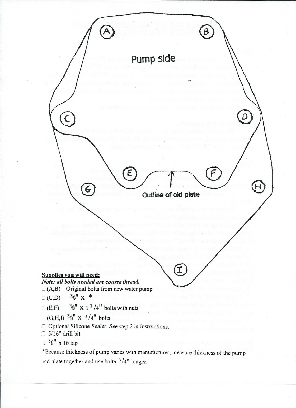
Instructions: